LED garland circuit 5 wires. Chinese garland: diagram, repair. LED garland diagram
Hello friends! Fabulous times are coming: children and adults have holidays, a Christmas tree on the balcony, vodka and sausage in the refrigerator.
Have you brought the tree in yet? Are you dressing up? Clear. And they probably saved on the garlands; there was enough for sausage.
Then take your time. Conduct an audit of the Chinese brothers' products before wrapping them on the holiday tree.
Chinese garlands are good at a low price. This is where the delights end, and the troubles begin: from dying out in the midst of fun to electric fireworks with a fire.
Option one, classic
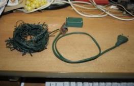
Photos of my fellow countryman Pavel Shepelev.
A garland of painted incandescent light bulbs, a control unit in a green box.
Scenario: turn it on to check, we get “BDYSHCHCH!” with fire and stench, the plastic was already leaking. The control unit has completely burned out, the reasons cannot be guessed.

Treatment: screw the green box, garlands in parallel. The garlands shine, but they don’t blink.
Option two, fashionable

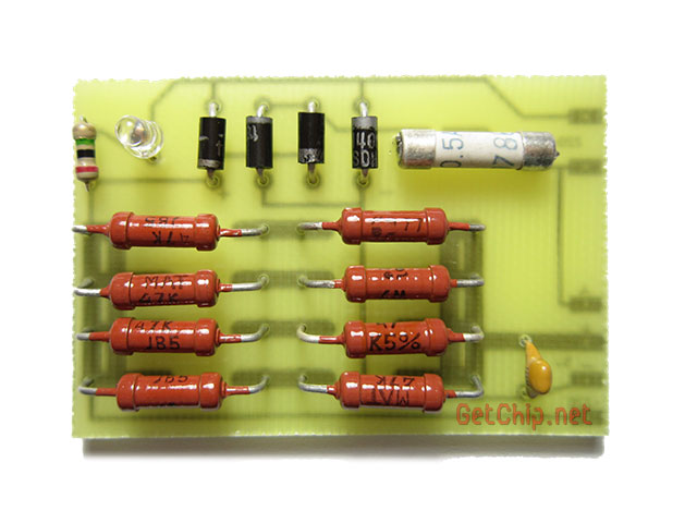
Multi-channel, multi-mode LED garland. Looks good to everyone: bright and colorful and not afraid of shocks, BUT! The Chinese have once again done something even more clever for economic reasons. In series with each branch of the lights there is a 3 kOhm resistor and some inhumanly low power, I believe - less than 0.125 W!
There are 10 such resistors in total. and they all warm themselves fiercely. And the meanness is that it is not noticeable. You won’t even realize the existence of these resistors until they start to burn - they are mounted so cleverly.
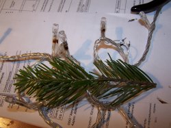
This garland worked for 1 NG. This is what was discovered during inspection today.

Low-power resistors overheated, burned, and even became unsoldered from LEDs and wires. Only the outer plastic clip held them in place. When disconnected, the solder cooled down and everything could be started all over again.
The malfunction did not appear!

The standard resistor is next to the 0.25W resistor.

I decided to install more powerful resistors and observe. The plastic clip was cut with a utility knife, the resistor was replaced. The procedure was performed for all detected resistors.
This article offers an excellent selection of diagrams for New Year's garlands and other electronic toys for the New Year's interior, based on the principles of autonomous and economical power supply, as well as the simplicity and reliability of assembling amateur radio structures.
LEDs of various types are used as the main radio component emitting light in all garland circuits. First of all, this allows you to significantly reduce the consumption of the battery source, as well as achieve unique and unpredictable New Year's pictures on a magical night.

Children are very fond of interesting and unusual things, especially flashing lights, so to the delight of the little ones, I suggest assembling a fairly simple version of the mini garland scheme. A printed circuit board in the popular amateur radio format Sprint Layout is attached in the archive above.

The circuit consists of a clock pulse generator on a domestic digital chip DD1 type K155LA3, the “power” part is made of bipolar transistors VT1-VT4, you can use almost any n-p-n structures, even KT315, if you still have them of course. An LED load and “switches” on logic elements DD2-DD4 with RC circuits R5C2, R7C3 between them are connected to the Transistors to set the turn-on delay time of the three output semiconductors.

In general, “children's joy” works as follows: Pulses follow from the generator to DD1.2, then opens VT2, then C2 is charged and as soon as the voltage on it reaches the level of logical unit “1”, then the output of element DD1.3 will also be unit that opens VT3. With DD1.4 the work is similar. The switching frequency is adjusted by selecting C1. As a result, a feeling of running lights appears.
I bring to the attention of readers diagram of a simple New Year's flasher, which can be originally made in the shape of a cross as a souvenir for the Easter or Christmas holidays. The shape of the flasher can be easily changed and used as an element of illuminated advertising.
The schematic diagram is shown in the figure. The LEDs are arranged in the shape of a cross, the circuit is made using the K561LA7 microcircuit. A rectangular pulse generator with a frequency of about 1 Hz is assembled on elements DD1.1, DD1.2, C1, R1, the transistor switch VT1 provides the necessary current for the HL1 LEDs. . . HL10, capacitor C2 is necessary if you need a smooth increase and decrease in the brightness of the LEDs - this is more pleasing to the eye. The resistance of resistors R3... R6 is selected (270-620 Ohms) so that the LED glow level is the same. Switch SA1 can be used to turn the display off or on in continuous lighting mode.

In this scheme, the number of LEDs can be increased to 12, from which you can create various decorative geometric shapes. If you use imported LEDs such as AND123R, which have appeared on our radio markets, the brightness of the glow will increase significantly.
This simple scheme is thirty years old, but it works great every new year in our home. The circuit is powered by a parametric stabilizer based on a D814D zener diode. The master oscillator is made on a K176IE12 counter with a quartz resonator with a period of 1 second. The signal from the counter output goes to a decoder made on the K561IE8 microcircuit. Positive pulses from its outputs are sent through diodes to the KT315 transistor, and the thyristor opens.

For a softer and more comfortable cozy glow, it is better to use ordinary light bulbs, which with both branches fit into the bridge rectifier and light up at full intensity. At the moment when the thyristor opens, some of the lamps are bypassed and the rest begin to glow at full intensity - this must be taken into account. The transformer can be taken from an old TV.

The circuit has mains voltage isolation, and even if you accidentally touch the power wires of the lamps, no harm will happen.
I think everyone will recognize the circuit of this simple multivibrator for two channels on two transistors. There can be many LEDs in each arm. Well, why not a super simple New Year's flasher that can be assembled on a circuit board in 5 minutes.

And if you want to use three arms, you can recall from an electronics course a multivibrator circuit with three transistors.


A correctly assembled circuit starts working immediately. Supply voltage from 5 to 9 V. Flashing frequency, i.e. The pulse sequences are selected using capacitors. It is advisable to use low-power LEDs with the same parameters.
Let's look at several simple circuit implementations. The first diagram reproduces the effect of “running lights” for three garlands. The basis is a circuit of three inverters of the K555LN1 digital microcircuit. The circuit works in such a way that at any given time only one of the inverters has a signal; accordingly, only one of the three garlands lights up, and the next one lights up when the previous one goes out.

The second circuit also allows you to achieve the effect of “running” lights, but with the ability to regulate the speed of switching the garlands, using a rectangular pulse generator. The switching frequency of the garlands is changed using resistor R3.

Another version of the Christmas tree garland switch circuit is similar to the previous one, but is assembled on CMOS chips and the frequency is adjusted by resistor R2.

The circuit is used to control a Christmas tree garland. A thyristor control module is built on bipolar transistors VT1, VT2 and resistors R3-R6. The flash frequency of the garland can be adjusted within a wide range by changing the parameters of the resistances R1, R2 and capacitor C1.

Among the many lighting devices used to decorate New Year trees, the Chinese garland design occupies a special place. It, like all similar Chinese products, is simple and cheap. There is a lot of controversy about the reliability of such garlands, however, most consumers use them.
Diagram of a classical Chinese garland
This design is equipped with smooth brightness control. For this, phase control is used to regulate the opening angle of the thyristors. Automation uses as many as eight programs that provide a wide variety of control algorithms. Due to its qualities, the device is very cheap, which is why it sells in millions of copies.
The controller is based on a small board with space provided. A microcontroller with four outputs is also located here. It is a small piece of genitax, where a microchip is attached using epoxy resin. Through the outputs of the microcontroller, using current-limiting resistors, four thyristors are controlled. This device is designed for anode voltage up to 600 volts and a current in the range of 0.6-0.8 amperes. In some designs of cheap garlands, instead of the input diode bridge, one diode remains. At the same time, the electrodes that control the thyristors are connected directly to the microcontroller outputs, without limiting the current.

As a rule, the power of the microcontroller is very small, therefore, it is not able to control the operation of powerful triacs. In order to solve this problem, it is necessary to use a separate low-power power source that is galvanically isolated from the general network. For these purposes, you can use a low-power adapter, for example, one that powers a television antenna amplifier that contains a stabilizer in its circuit.
Other ways to solve problems
To combine a low-power microcontroller with powerful triacs, it is practiced to use transistor switches, where transistors with a high current gain are used. Thus, the Chinese garland circuit does not overload the microcontroller outputs. To ensure galvanic isolation, special microcircuits are used, the input of which contains an LED, and the output has a low-power triac.
In order for the Chinese garland to work normally, it must be synchronized with the network using a signal. For this purpose, a phase with a nominal value of 220 volts is supplied to the input of the microcontroller through an installed resistor. The neutral wire of the network is connected to the common wire of the entire device.
Replacing the Chinese garland control unit
The New Year is coming soon! Christmas tree decorations appear on store shelves next to tangerines, sweets and champagne: multi-colored balls, tinsel, all kinds of flags, beads and, of course, electric garlands.
You probably won’t be able to buy a regular garland of multi-colored light bulbs. But there are simply countless different flashing lights, mostly made in China. Microscopic bulbs can be placed on a piece of cardboard or woven into a carpet of wires that can be used to decorate an entire window at once.
Christmas tree garlands are also distinguished by great variety, especially in appearance and design. The cost of such garlands is low, as is the power of the light bulbs.
Most garlands have a small plastic box with one button, a cord with a power plug and wires going to a garland of multi-colored light bulbs. The design of the garland can be very diverse.
The simplest and cheapest option consists of microscopic light bulbs inserted. On the back of the packaging box there are instructions for replacing the bulbs and safety precautions, although no spare bulbs are included. These are the garlands that are sold in the “Everything for 38” chain of stores, although recently they have sold for forty rubles.

Figure 1. Garland for forty rubles
Garlands of another style have small plastic shades on the light bulbs, for example, in the form of transparent flowers with petals. But the box with the button remains the same, although the price of the garland reaches up to two hundred rubles. Let's try to open the box and see what's inside.
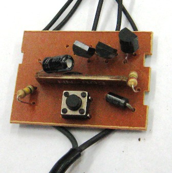
Figure 2. Appearance of a garland controller with three thyristors
At the bottom of the figure two wires are shown; this is how the device is connected to the network. There is also a button here that switches operating modes. In the upper part you can see three thyristors and wires going to the garlands.
In the middle of the board there is a black drop mounted on a small printed circuit board. The board has contact pads with which the controller is soldered into the main board.
How many thyristors are on the board
The control electrodes of thyristors, which turn on strings of light bulbs, are connected to the outputs of the microcontroller. The microcontroller has four outputs, but often, instead of four thyristors, only three are installed on the board, and in some cases only two.
The necessary visual effect is achieved by connecting garlands and placing light bulbs: light bulbs of two or even three colors are sealed in one garland. Just such a board is shown in Figure 2.
If you look at this board from the printed circuit board, you can see that three thyristors are soldered, and under the fourth there are holes with tinned contact pads, as shown in Figure 3. In some cases, the holes are not even drilled, they say, whoever wants to drill it himself .

Figure 3. Garland controller board. Free space for thyristor
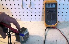
Here it is worth noting this feature: if the controller output is not connected anywhere, this does not mean that it is not working. The program in all controllers is apparently the same, all controller outputs are used.
This can be easily verified using a pointer tester. If you measure the constant tension on the free leg, the needle will jump, twitch and deviate along with the blinking of other garlands. It is enough to simply solder the missing thyristor into the board, and, please, we get a full-fledged four-channel garland.
The thyristor can be taken from an old faulty board (it happens that the controller becomes unusable) or you can buy an additional garland for forty rubles and remove the thyristor from there. For a good cause, the costs are extremely small!
Schematic diagram of the garland
It is not difficult to draw a circuit diagram using a printed circuit board. There are two types of schemes, slightly different from each other. The first, most advanced option is shown in Figure 4.

Figure 4. Chinese garland controller. Option 1
The entire circuit is powered via VD1...VD4. The garlands are powered by pulsating voltage and are turned on by the controller through thyristors VS1...VS4. Resistor R1 and microcontroller DD1 form a voltage divider, the output of which is a voltage of 12V.
Capacitor C1 smoothes out the ripples of the rectified voltage. Through resistor R7, the mains voltage is supplied to the input of controller 1 to synchronize the circuit with the 220V mains frequency, which allows for phase control of the thyristors. This synchronization allows for smooth ignition and extinction of the garlands. These are the types of boards that can be found in expensive garlands.
The board shown in Figure 3 is assembled according to a somewhat simplified circuit, which is shown in Figure 5.

Figure 5. Chinese garland controller. Option 2
It immediately catches your eye that there are only three thyristors, and only one diode remains from the rectifier bridge. Resistors also disappeared from the control electrodes of the thyristors. But, in general, the consumer properties remained the same as in the previous circuit, despite the fact that the light bulbs light up only when there is a positive half-cycle of the mains voltage on the upper wire of the circuit. Without a rectifier bridge, half-wave rectification is obtained.
This version of the circuit design is inherent in those garlands that are “all forty”. That, in fact, is all that can be said about the circuit design of Chinese Christmas tree garlands.
How to connect powerful lamps
The power of the garlands is low, the bulbs are simply microscopic, and they are unlikely to fit anywhere else besides a home Christmas tree. But sometimes it is necessary to connect a garland with powerful incandescent lamps, for example, for decorative lighting of building facades. This modification has already been given in the article. The diagram of the modified garland is shown in Figure 8 in the mentioned article.
If you don't want to remake the board
It is much easier to do without reworking the controller board. All you have to do is make four powerful output switches with optocoupler isolations and connect them instead of low-power garlands. The power switch circuit is shown in Figure 6.

Figure 6. Powerful power switch with optocoupler isolation
Actually, the scheme is typical, it works flawlessly, and does not contain any pitfalls. As soon as the LED of the MOC3021 optocoupler lights up, the low-power optocoupler thyristor opens and the control electrode and the anode of the BTA16-600 triac are connected through pins 4, 6 and resistor R1. The triac opens and turns on the load, in this case a garland.
An optocoupler should be used without a built-in CrossZero circuit (line voltage zero crossing detector), for example, MOC3020, MOC3021, MOC3022, MOC3023. If the optocoupler has a CrossZero node, then the circuit WILL NOT WORK! This should not be forgotten.
The BTA16-600 triac has the following parameters: forward current 16A, reverse voltage 600V. At a current of 5A and a voltage of 220V, the load power is already a whole kilowatt. True, you will need to install a triac on the radiator.
The metal substrate is isolated from the crystal, as indicated by the letter A in the triac marking. This makes it possible to install triacs on a radiator without mica spacers and insulators for the screw. By the way, it is these triacs that are used in the power regulators of household vacuum cleaners, while the radiator is blown by the air flow at the outlet of the vacuum cleaner.
If the load power is no more than 400W, then you can do without a radiator. The pinout of the triac is shown in Figure 7.

Figure 7. Pinout of triac BTA16-600
This drawing will come in handy when assembling a power switch circuit. It is best to assemble all four power switches on a common printed circuit board. It is better to assemble resistor R from two 2W resistors, which will avoid their excessive heating. The maximum current of the input LED of the optocoupler is 50mA, so a current of 20...30mA will ensure its long-term trouble-free operation.

Figure 8. Connecting power switches to the controller board
In general, everything is clear and simple. The garlands are unsoldered from the controller, and the input circuits of the power switches are soldered in their place. In this case, no intervention is required in the printed circuit wiring of the controller. The only exception is the soldering of an additional thyristor, provided that it can be found. You will also have to make the power cord and plug somewhat thicker, since the original one has a very small cross-section.
If installed correctly and the parts are in good working order, the circuit does not need to be configured. The design of the device is arbitrary, preferably in a metal case of suitable dimensions, which will act as a radiator for triacs.
To ensure electrical safety, the device should be turned on via a circuit breaker, or at least a fuse.
The New Year holidays are approaching and on this occasion I want to do something bright and festive! I decided to make a New Year's garland. What could be brighter and more festive than a New Year's garland? :). I decided to make not a simple garland, but a sophisticated one! 12 channels plus control from an IR remote control. In order not to make a garland from scratch, it was decided to use donors internal organs For spare parts, use ready-made Chinese garlands. This makes sense for the following reasons:
— the cost of the garlands, let’s be honest, the cost is a pittance. Try to buy wires, LEDs, spare parts for the same money... And if you don’t take an LED garland as your goal, then light bulb garlands are now sold for almost nothing;
— an important factor is ready-made LED lines soldered together. Soldering yourself, heat shrinking, making mistakes and redoing 12 lines is quite a tedious job;
- yet, I don’t know about you, but I have a certain number of non-working garlands lying around (they are often brought to me to repair them - and they end up) you can not spend money on new ones at all, but collect them from what you have.
To get started, watch the video:
ATTENTION!
dangerous voltage 220V!
LIFE THREATENING!
THAT'S WHY:
If you realize the danger assembling such a garland and undertake to comply with safety rules when working with dangerous voltage, you can read further about how to assemble a super garland.
1 Garlands patients.
As sacrifices, 3 new LED garlands were purchased - they are beauties :)
Cost $3 per piece (100 LEDs). But if the Chinese don’t save, they will cheat on themselves! In fact, the garlands contained 3 channels. That is, the controller itself is four-channel, but there are three thyristors and three LED lines. In order to disguise such disgrace, the Chinese mix LEDs of two colors in one line. In short, I had to buy another one :(. But this is not the limit of savings, there are often two channels at all! Be careful - open the box and see how much the thyristors cost.

From the original controllers for the improved garland, resistors, rectifying diodes, thyristors, a button, and boxes will be used. You will need to buy a little more than a dozen resistors, a couple of capacitors, an ATtiny2313 microcontroller and other little things.
2 Scheme.
Here is a diagram of the original garland:

The diagram shows that dimming of LED channels is carried out by thyristors PCR406
Datasheet for thyristor PCR406
I don't see any point in changing them to something else. To generate the supply voltage of the original controller, a quenching resistor is used (the quenching resistor, together with the internal resistance of the controller, forms a voltage divider). The solution is controversial, but in this case it is justified by its low cost (the controller current is insignificant and the power allocated to the resistor is very small). Having weighed the pros and cons of such a decision, I decided to do something similar in my scheme. True, the ATtiny2313 current (within 8mA) is significantly higher than the original controller, but still allows the use of quenching resistors.
Diagram of the new garland controller:
6 Assembling the power supply board.
Before assembling the power supply board, you need to make certain measurements to calculate the value of the quenching resistors. To do this, we connect the soldered controller board with the firmware microcontroller to an EXTERNAL 5 volt source (+5v and -5v pads) and measure the current consumption. It is not necessary to connect the LED lines; they have virtually no effect on the current consumption. For a regular ATtiny2313 microcontroller without letter indices, the current consumption should be about 7 - 9 mA. For an ATtiny2313 microcontroller with indices (maybe A, P...) the current will be different.
Based on the received current consumption (Ipot), we calculate the resistance of the quenching resistors in the battery (we accept the larger one from the standard range):
R = 430 / Ipot
For example, my current consumption was 9 mA, which means R = 430 / 0.009 = 47777 Ohm (assuming 47 kOhm).
The stacking of quenching resistors is designed to distribute power dissipation and reduce heating. Resistors must have a power of at least 0.5 W (and preferably 1 W each).
The rectifying diodes and quenching resistor are migrated from the original circuit; the rest will have to be purchased. We place the finished board in the garland body.
We connect the power supply and controller boards (we take the wires and plug from the original garland). Don’t forget to secure the wires soldered to the boards with hot glue, since the wires used by the Chinese are, to put it mildly, crap and can fall off at any moment.
7 Formation of LED lines.
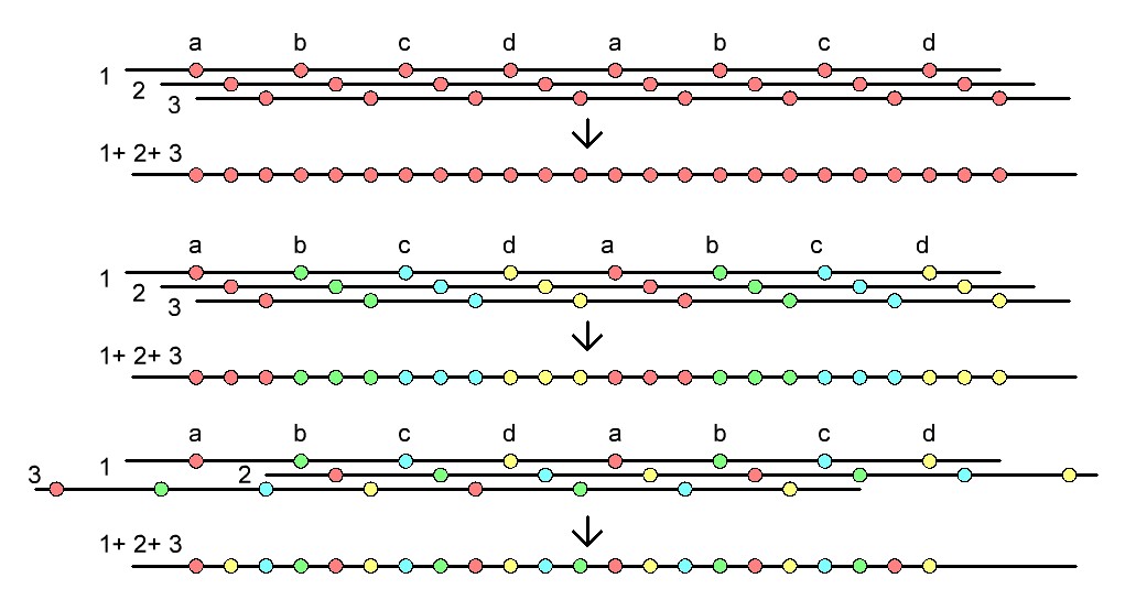
What you will have to tinker with is the formation of 12 channels of LED lines. It will be necessary to assemble a common harness with twelve lines (plus a common wire) from three bundles (and in the case of three channels in a garland, four bundles) of the original garlands. The garlands need not just be twisted together, but care must be taken to ensure that the LEDs of all twelve channels are arranged sequentially, one after the other. In addition, if the garland is multi-colored, you need to ensure that the colors are mixed as much as possible.
In general, for better visualization of effects, single-color garlands are better suited, but for creating a brighter image, multi-colored garlands, perhaps, win. Here you must decide either more expressive effects or a more colorful impression.
It takes a long time to explain in words - look at the pictures or think for yourself how to twist the bundles:
The harnesses are twisted - now we solder them to the controller so that the channel LEDs follow each other in series.
8 Description of the garland's operation.
When you plug the garland into the network, it immediately starts working with a random effect. During operation, the effects will randomly change each other. If you press the button, the effects will sequentially replace each other in turn:
1 Wave
2 Shooting Star
3 Sparks
4 Slow overflow
5 Running lights
6 Twinkling lights
7 Everything burns and goes out
8 Everything is on fire
0 All off
When you select an effect with the button, it lingers for a longer time, but later the effects will begin to replace each other again.
Operation from the remote control is similar to the operation of the button on the controller (press the button on the remote control - the effects change sequentially). To study the button of any IR remote control, you need to hold down the button on the controller until the garland goes out (about 3 seconds), then you need to press the selected button on the remote control. The button code will be written into non-volatile memory and the garland will return to the effects. Since the code is stored in non-volatile memory, the garland will “remember” the remote control even after being disconnected from the network.
Finally, I think it’s worth reminding:
ATTENTION!
The garland circuit is not galvanically isolated from the network dangerous voltage 220V!
Touching any conductive part of the garland connected to the network
LIFE THREATENING!
THAT'S WHY:
- if you are not well versed in electricity, do not repeat this design;
— any actions (soldering, measurements, etc.) with the circuit must be performed only after disconnecting from the network;
— programming the microcontroller must be done either separately from the board (for example, in a breadboard specially assembled for this purpose), or by powering the garland board from an external 5 volt source (for example, from batteries);
— the finished structure must be well insulated and inaccessible to small children and animals;
- Be careful when assembling the structure!
And here are examples, so to speak, live:
Send yours and I’ll add them here.
Christmas tree from AndreevKV. It turned out big! 🙂
Christmas tree from BOYka59. All my friends and especially the children are delighted with her)
And further!
Happy New Year!
Good mood and happy holidays to everyone!
Update 1 (2013)
I didn’t really plan to do anything with this garland, since I don’t have time for it this year, but at the request of readers I still decided on a small update!
Little changed.
Added 6 new effects:
— a wave of 2 LEDs running in different directions
— sequential filling and decreasing
— sequential filling and decreasing with a variable traveling wave
- random filling and deletion
- random filling and removal with variable traveling wave
- aggressive flicker
The operating time of the effect when forced switching (remote control or button) is almost doubled.
That's all. The circuit and fuses remain the same. It is necessary to re-upload the new firmware.
- 12-channel super garland (update 2013)
- Source of the supergarland update
Happy coming, now, 2014!!! 😉
Super garland options from blog readers
Sergey Cherniy (Bleck_S)
The garland is implemented on one board using SMD components