The dependence of the pressure from the centrifugal pump. Characteristics of pumps. Types of characteristics. The concept of the optimal zone of the characteristics of the pump. Summary charts of pump nomenclature
Performance (q) is usually expressed in cubic meters per hour (m 3 / hour). Since liquids are absolutely incompressible, there is a direct relationship between performance, or consumption, pipe size and fluid velocity. This attitude is:
Where ID is the inner diameter of the pipeline, inches
V - fluid speed, m / s
Q - performance, (m 3 / hour) 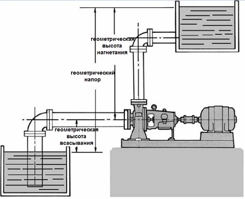
Fig. 1. Suction height - shown geometric pressure in the pumping system, where the pump is above the suction tank (static pressure)
Power and efficiency
The work performed by the pump is a function of general pressure and fluid weight pumped for a given period of time. As a rule, the formulas use the pump performance parameter (m 3 / hour) and liquid density instead of weight.
The power consumed by the pump (BHP) is the actual power on the pump shaft communicated by the electric motor. The power at the outlet of the pump or hydraulic (WHP) is the power communicated by the liquid medium. These two definitions are expressed by the following formulas. 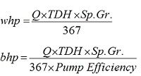
Power at the pump inlet (power consumption) is greater than the power at the outlet of the pump or hydraulic power due to mechanical and hydraulic losses arising in the pump.
Therefore, the effectiveness of the pump (efficiency) is defined as the ratio of these two values. ![]()
Speed \u200b\u200band type of pump
SPECIFICATURE is a calculated coefficient used to classify the pumping wheels of the pump and sizes. It is defined as the frequency of rotation of the geometrically similar impeller supplying 0.075 m 3 / with a fluid under the pressure of 1 m. (In American units of measurement 1 gallon per minute at 1 feet of pressure)
However, this definition is used only in engineering design, and the speed should be understood as a coefficient for calculating certain characteristics of the pump. To determine the coefficient of speed, the following formula is used: 
Where n is the pump speed (in turns per minute)
Q - performance (m 3 / min) at the point of maximum efficiency.
H - pressure at the point of maximum efficiency.
Specific determines the geometry or class of the impeller, as shown in Fig.3. 
Fig. 3 Wheel shape and speed
As speed gain increases, the relationship between the outer diameter of the imperial wheel D2 and the input diameter D1 is reduced. This ratio is 1.0 for the impeller impeller.
Wheels with radial blades (low NS) create pressure at the expense of centrifugal force.
Pumps with higher NS create pressure partly using the same centrifugal force, and partly with the help of axial forces. The higher the coefficient of speed, the greater the share of the axial forces in the creation of pressure. The axial flux pumps or the propeller with the ratio of 10,000 (in American units) and above create pressure exclusively at the expense of the axial forces.
The wheels of the radial stream are usually used when a high pressure and low performance is needed, while the axial flux wheels are used for pumping large volumes of fluid at low pressure.
Cavitational reserve (NPSH), inlet pressure and cavitation
The hydraulic institute defines the NPSH parameter, as the difference between the absolute pressure of the fluid at the entrance to the impeller and the pressure of saturated vapor. In other words, it is the excess of the internal energy of the fluid at the entrance to the impeller on its pressure of saturated vapor. This ratio allows you to determine whether the liquid will boil in the pump at the point of minimum pressure.
The pressure that liquid has on the surrounding surfaces depends on temperature. This pressure is called saturated vapor pressure, and it is a unique characteristic of any fluid, which increases with increasing temperature. When the pressure of a saturated pair of liquid reaches pressure ambientThe liquid begins to evaporate or boiled. The temperature at which this evaporation occurs will be reduced as the environment is reduced.
When evaporation, the liquid increases significantly in the amount. One cubic meter of water at room temperature is converted to 1700 cubic meters of steam (evaporation) at the same temperature.
From the foregoing it is clear that if we want to effectively pump the liquid, you need to maintain it in a liquid state. Thus, NPSH is defined as the value of the valid height of the pump suction, at which the evaporation of the pumped fluid does not occur at the point of the minimum possible fluid pressure in the pump.
The required NPSH value (NPSHR) depends on the design of the pump. When the fluid passes through the suction pipe of the pump and falls on the impeller guide apparatus, the fluid speed increases, and the pressure drops. Also arise pressure loss due to turbulence and irregularity of fluid flow, because Liquid beats over the wheel.
The centrifugal force of the impeller blades also increases the speed and reduces fluid pressure. NPSHR is the necessary suboro on the suction pipe of the pump to compensate for all pressure losses in the pump and keep the fluid above the level of pressure of saturated vapors, and limit the pressure losses arising from cavitation at the level of 3%. Three-percentage of pressure drop is a generally accepted NPSHR criterion, adopted to facilitate the calculation. Most low suction pumps can work with a low or minimum NPSHR reserve, which does not seriously affect their operation. NPSHR depends on the speed and performance of pumps. Usually pump manufacturers provide NPSHR characteristics information.
The valid NPSH (NPSHA) is the characteristic of the system in which the pump runs. This is the difference between atmospheric pressure, the height of the pump suction and the pressure of saturated vapor. The figure shows 4 types of systems, for each presented formulas for calculating the NPSHA system. It is also very important to take into account the density of the fluid and lead all the values \u200b\u200bto one unit of measurement.

Fig. 4 Calculation of the fluid column over the pump suction nozzle for typical suction conditions
PV - atmospheric pressure, in meters;
VR is the pressure of saturated vapor of fluid at the maximum operating temperature of the fluid;
P is the pressure on the surface of the liquid in a closed capacity, in meters;
Ls - maximum suction height, in meters;
LN - the maximum height of the subel, in meters;
HF - friction losses in the suction pipe with the required pump performance, in meters.
The real NPSHA system is determined using the testimony of the pressure gauge installed on the suction side of the pump. The following formula applies:
Where GR is the testimony of the pressure gauge on the suction of the pump, expressed in meters taken with a plus (+), if the pressure is above atmospheric and minus (-), if below, adjusted to the axial line of the pump;
HV \u003d Dynamic pressure in the suction pipe, expressed in meters.
Cavitation is a term used to describe the phenomenon occurring in the pump with an insufficient NPSHA. The fluid pressure is lower than the pressure value of saturated vapors, and the smallest bubbles of the pair of liquid, move along the blades of the impeller, in the region high pressure Bubbles are quickly destroyed.
Destruction or "explosion" is so fast that it may seem like a rumble, as if gravel poured into the pump. In the pumps with a high suction ability of bubbles explosions as strong that the blades of the impeller are destroyed in just a few minutes. This effect may increase under certain conditions (very high suction ability) can lead to serious erosion of the impeller.
The cavitation appeared in the pump is very easy to recognize according to the characteristic noise. In addition to damage to the impeller, cavitation can lead to a decrease in pump performance due to the fluid evaporation occurring. When cavitation may decrease the pressure of the pump and / or become unstable, the power consumption of the pump can also be non-permanent. Vibrations and mechanical damage such as, for example, damage to bearings, can also be the result of the operation of the pump with a high or very high suction ability during cavitation.
To prevent the undesirable effect of cavitation for standard low absorbency pumps, it is necessary to ensure that the NPSHA system is higher than the NPSHR pump. High suction pumps require reserve for NPSHR. Standard of the Hydraulic Institute (ANSI / HI 9.6.1) proposes to increase NPSHR 1.2 - 2.5 times for pumps with high and very high suction ability, when working in the permissible range of performance.
The pump is a hydraulic machine that converts the mechanical energy of the drive motor into the energy of the liquid that ensures its movement. Based on the functional purpose of the pump that determines the technical parameters are the supply and pressure (pressure). In the volume of the liquid supplied by the pump per unit; time expressed in m3 / hour (cubic meters per hour) or l / s, (liters per second). It is denoted by "q". Thenor is the difference of specific anegs of fluid in sections after and to a pump, expressed in the meters of water column. Denotes "H". In the pumps of volumetric type, use the concept of "pressure", expressed in the atmospheres (kgf / cm) or megalaskal (MPA) (one megapascal is 10 atmospheres). The name characteristic reflects the main consumer properties, pump. The selection of the pump begins with the selection of pressure (pressure) and the feed. When the pump selection should be taken into account the variation of the pump parameters for the supply and pressure, including with different handwriting of the impeller, as well as the possibility of finding the required mode of operation within the working area of \u200b\u200bits characteristics.
An important hydraulic parameter of the pump is the allowable vacuum absorption height, which characterizes the normal conditions of the fluid approach to the impeller. This value is expressed in the meters of a water column at a temperature of 20 ° C and at normal atmospheric pressure (10 m of water. Art.). Due to various reasons, including due to the complexity of the physical process that occurs not to absorb the pump, this most important parameter during operation and during the selection of pumps is not paid due attention. Graphic image of the pressure characteristics of centrifugal pumps is usually a common curve that decreases For greater feed. In other words, with a greater supply, we have a smaller pressure and on the contrary. For each pump design, there is its own pressure characteristic, determined by the steepness and maximum quantity of kp., I.e. zone of optimal work. The pump working point on this curve is determined by the "network" resistance. If you change the resistance of the network. For example, closing the valve, the operating point will shift to the left by the curve, i.e. The pump will choose the mode of operation at a smaller feed, as "is forced to" work with high pressure to overcome additional resistance.
There is another way to change the working conditions of the pump on the network - this is bypassing, i.e. Installation of adjustable or unregulated bypass (bypass) from the pressure line to suction. In relation to the pump, it is similar to a decrease in resistance, i.e. There is a decrease in pressure. In relation to the consumer network, it is similar to a decrease in filing. As a result, the operating point (Q - H) will shift cool down, i.e. We can in the consumer network get a smaller pressure at the same time and smaller.
Determination of the concept of pressure
Increased pressure pump is called pressure. Under the pressure of the pump (H) it is understood as the specific mechanical work transmitted by the pump of the pumped liquid.
H \u003d E / G [M]
E. \u003d Mechanical Energy [N M]
G. \u003d weight of the pumped liquid [H]
At the same time, the pressure generated by the pump, and the flow rate of the pumped liquid (feed) depends on each other. This dependence is displayed graphically as a pump characteristic. The vertical axis (ordinate axis) reflects the pump pressure (H), expressed in meters [m]. Other scales of the pressure scale are also possible. The following ratios are valid:
10 m V.ST. \u003d 1 bar \u003d 100,000 Pa \u003d 100 kPa
On the horizontal axis (abscissa axis) caused a pump feed scale (q), expressed in cubic meters per hour [m3 / h]. Other scales of the feed scale are also possible, for example [l / s]. Form Characteristics Shows next species Dependencies: The energy of the electric drive (taking into account the total efficiency) is converted into the pump into such forms of hydraulic energy as pressure and speed. If the pump is working with the valve closed, it creates maximum pressure. In this case, they say about the pressure of the pump H 0 at zero feed. When the valve begins to slowly open, the pumped medium comes into motion. Due to this, part of the drive energy is converted into the kinetic energy of the liquid. Maintaining initial pressure becomes impossible. Characteristic of the pump acquires the shape of a falling curve. Theoretically, the pump characteristic intersects with the feed axis. Then water has only kinetic energy, that is, pressure is no longer created. However, since in the system of pipelines always takes internal resistance, in reality, the characteristics of pumps are broken before the supply axis is reached.
- Characteristics of pumps
- Various steepness with an identical case and a working wheel of pumps (for example, depending on the rotational speed of the motor) The form of characteristics shows the following dependencies:
The cause of the hydraulic resistance occurring in the pipeline network is the friction of water on the walls of the pipes, friction of water particles by one friend, as well as a change in the flow direction in the shaped parts of the reinforcement. When the feed changes, for example, when opening and closing the thermostatic valves, the flow rate is also varied and, thereby resistance. Since the cross-section of pipes can be considered as the area of \u200b\u200bthe live cross section of the flow, the resistance changes quadratically. Therefore, the chart will have a parabola form. This relationship can be represented as the following equation: H1 / H2 \u003d (Q1 / Q2) 2.If the supply in the pipeline network is reduced twice, then the pressure drops by three quarters. If, on the contrary, the feed increases twice, then the pressure rises four times. As an example, it is possible to take out the expiration of water from a separate water tap. In the initial pressure of 2 bar, which corresponds to the pressure of the approx. 20 m, water leaks from the CRANT DN 1/2 with a flow rate of 2 m3 / h. To increase the flow twice, it is necessary to increase the initial pressure at the inlet from 2 to 8 bar.
Working pointThe point in which the characteristics of the pump and the system intersect is operating point system and pump. This means that at this point there is an equilibrium between the useful power of the pump and the power consumed by the pipeline network. The pump pressure is always equal to the resistance of the system. This also depends on the feed, which can be provided by the pump. If this should be borne in mind that the feed must not be lower than a certain minimum value. Otherwise, this can cause a too strong temperature increase in the pumping chamber and, as a result, damage to the pump. To avoid this, it is necessary to strictly follow the manufacturer's instructions. The operating point outside the pump characteristic may cause damage to the motor. As the feed changes during the pump, the operating point is also constantly shifting. Find the optimal estimated work point in accordance with the maximum operational requirements included in the task of the designer. These requirements are: for circulating pumps heating systems - heat consumption by building installations of increasing pressure - peak consumption for all places of waterborg. All other operating points are located on the left of this calculated working point. The two figures are shown the effect of changing the hydrodynamic resistance to the displacement of the operating point. The displacement of the working point in the direction of the left of the calculation position inevitably causes an increase in the pressure of the pump. As a result, noise in the valves arises. Adjusting the pressure and submission in accordance with the need can be used by the use of pumps with a frequency converter. At the same time, operating costs are significantly reduced.
C.O.K. N 3 | 2010 Category: Plumbing and Water Supply
Often it is necessary to deal with the incorrect work of the heating system due to the wrong selection and installation, which is happening when you try to save on the design. At the same time, the pump is often selected by the client itself based on its empirical ideas about the necessary characteristics. Unfortunately, sometimes the situation occurs when assistance in the selection of the pump by the client has an inexperienced consultant, which also leads to miscalculations.
The errors described in the article, at first glance, are so obvious that a qualified engineer may be incomprehensible as they can be allowed at all. But practice says the opposite: more and more pumps are selected and installed without taking into account the features and basic characteristics of the heating system, both individually and in high-rise construction. If the first at least somehow can be explained by the inexperience of a homeowner and armpitality in the means, then the second is completely unacceptable, since the overhaul and maintenance of urban residential funds (at least, must lead) the organization with the relevant license.
Although the curiosities are different. For example, once a tender for the construction of an apartment building in one of the cities of Russia won a foreign company, which provided for the competition only a colorful 3DRINS. Not drawings, no calculations were available. But the offer turned out to be the most profitable in financially. And found no absence project documentation Only the managers of the company, which was supposed to mount the heating system in the building, when construction has already begun.
But back to the pumps. As a result of the wrong choice of such, it would seem, minor and small in size of the device as a circulation pump heating in the house functions unsatisfactory. The dissatisfied client is looking for a problem in the boiler, radiators and a general project. But sometimes it is enough to critically evaluate the characteristics of the pump and, if necessary, adjust them.
Recall the physical substantiation of the need for circulating pump. Heated water, as we know, can move through the pipes of the heating system and independently under the action of gravity force. The heated coolant having a smaller density rises up, freeing the place for the cooled, more dense coolant. But the rate with which natural circulation occurs does not always correspond to the calculated indicators, especially in small diameter pipes (DN15-20) due to overcoming hydraulic resistance. In order to bring the speed of the water circuit in the heating circuit in accordance with theoretical calculations, the circulation pump is used.
For proper selection The pump is required to take into account a number of parameters: the maximum pressure [m] is the maximum height that will need to raise the coolant; The maximum duct [m3 / h] is the maximum possible volume of the coolant, which will be required to pump per unit of time at full system load; passing diameter of the pipe DN [mm]; chemical composition coolant (water, non-freezing liquid or mixture thereof). The pressure and duct are needed to find the working point, passing diameter - for the convenience of mounting and taking into account the individual characteristics of the system, the chemical composition - to select the right model range of pumps. The pressure is responsible for the supply of heat carrier to the upper point of the heating circuit and overcoming hydraulic resistance, the duct for compensation for the heat loss of the room. From this and it is necessary to proceed with the elimination of miscalculations. Now more about typical errors, their causes and recipes.
Power Pump Selection
Although in the characteristics of the circulation pump and its power is indicated, this secondary parameter, the selection does not participate in the selection and serves only for a reference point so that the user gives itself a report in the amount of electricity consumed by the instrument acquired.
The pump is not a heating boiler, not convector, not, in no case cannot be selected by power per unit of service. The power of circulation pumps having the same pressure-consumable characteristics, but belonging to different classes of power consumption, can be very different.
Moreover, the more modern device, the less power it has, with other things being equal. For approximate estimation of the circulating pump economy, a letter classification is used for home appliances.
The class "A" indicates the lowest power consumption, class "B" - about low power consumption, the remaining letters usually do not put at all, because there is nothing to boasted here.
Possible four options for selecting the pump:
The operating parameters of the pump are redundant (see section "Using the pump with redundant characteristics");
The operating parameters of the pump are insufficient (probably a recommendation from the section "Selection of pumps on the maximum pressure" section);
The operating parameters of the pump correspond to the project (Congratulations, you are lucky this time, but do not hope that the next time will also be lucky, the method is still incorrect);
The pump completely does not fit: not that heat carrier, not the modification, not the purpose of the pump, finally (such a pump is used, of course, it is impossible).
Selection of pump for maximum pressure
The characteristics of the pump usually indicates its maximum pressure. Some on this figure are oriented: they say, I need to raise water four meters, just the opposition corresponding to 4 m. But the maximum pressure and the working point are different things. If you carefully look at the schedule reflecting the pressure-consumable characteristic (Fig. 1), it is easy to see that with the maximum pressure, the flow rate is zero. Therefore, it is necessary to calculate the so-called in advance. The "operating point" R, in which the lifting height will be taken into account, and the required duct, and after looking for a pump with suitable parameters (point d). As can be seen from the graph presented, the pressure that the selected pump can provide, differs from the maximum value indicated in the characteristics of the maximum value by about 20-25%. This is due to the fact that the height of the coolant lifting (i.e., usually, the height of the building) is easy, but the duct must be specifically calculated.
The described approach, unfortunately, is very common among inexperienced buyers and sellers. Moreover, it is not only devices for circulation of the coolant, but also other varieties pumping equipment: submersible, efficient, etc.
If in a small building, the flaws are not so noticeable, the apartment highways suffer from miscalculations of designers and installers is very and very significant. There are several examples when in new buildings or in old houses after major repairs in the lower floors of the lower floors, the temperature in the winter was higher than in the Sahara desert, the inhabitants of the top floors felt themselves polar explorers on the ice. After the studies and eliminate the obvious causes of the type of defective air vent and clogged radiators (which, by the way, is also good), as a rule, came to the conclusion that the pump "does not pull." The analysis of flights showed: when purchasing equipment was saved on the designer, hoping the experience of the seller or their strength.
You can correct the error in the installation of the additional pump sequentially (to increase the pressure, Fig. 2b) or in parallel (to increase the duct, Fig. 2B) with the already existing. To again not step on the same rake, it is necessary to remember that the actual pressure / duct will increase only slightly, the double increase is possible only in theoretical extreme points. Also, we should not forget that in the embodiment shown in Fig. 2B, only the pressure increases, the dashing will be equal to the operating characteristics of the most powerful pump of pumps. Similarly, in the diagram in Fig. 2B should not expect an increase in pressure.
Selection of pump on dimensions
Sometimes in individual construction there is a problem that prevents the installation of the pump with suitable characteristics exclusively due to its dimensions. This happens when, when assembling the system, the builders left such a little free space that the required additional node has no place to stick. And, instead of purchasing a convenient pump group, the unfortunate victim of the unskilled planning is forced to buy all the elements separately, it is also measuring them, and then twist them, rising chaotic curly pipes of other contours. The appearance of the strapping from this only worsens, free space is not added, it is difficult to get to the place of installation, and how to service this economy is generally scary to think.
If on the alteration of the whole strapping (and this is recommended) no money left, you can advise you to take the required pipelines to the side and mount the appropriate pump group away from the total intricacies. At least one contour will be correctly decorated, and it does not have to suffer because of the wrong pump.
Using a pump for non-freezing fluid
Our compatriots love to use non-freezing fluid as a coolant, especially if we are talking about heating systems with components operating from electricity. This is motivated by the fact that "if the electricity is disconnected, that in our village is not uncommon, the whole system will freeze." It does not take into account the fact that imported equipment, in general, is not calculated on our Tosol.
First, to prevent such cases, IPB (uninterrupted power sources) have been invented many years ago, which in our market exist now both in imported and in domestic performances. Here are these devices and you need to use so that the system does not stop working. After all, in addition to the actual disabilities, the voltage jumps can also take place, which IPB will successfully smooth.
Now about non-freezing mixtures. We will not concern other nodes of the heating system now, we will not discuss the destruction of individual components due to their reaction with glycols, bringing and depressing the system, toxicity and fire hazard of alcohols, weakly predicted heat transfer and other "charms".
Let us dwell on the pump and the most common non-freezing fluid - ethylene glycol.
Ethylene glycol and its mixtures have 2-4 times greater viscosity than water, and the pump will need more powerful compared to the calculated traditional way. The experimental way is established that it is necessary to provide a margin on the pressure of about 50-60% and in terms of performance about 10-15%. The manufacturer's instructions are usually written that the device is allowed to be used exclusively for pumping distilled or close to it in the composition of water. In exceptional cases, it is allowed to operate with water-leaky mixtures in the content of glycol, most often, not more than 20%. The meaning of this warning is that. In the pumps with a wet rotor, the cooling of the motor occurs the most pumped liquid, which comes through the grid of small holes. The diameter of the holes is designed in such a way that water passes through them with the speed required for optimal cooling. Molecules of polyhydric alcohols - organic compounds with hydroxyl groups (for example, ethylene glycol formula: Ho - CH2 - CH2 - OH) is much larger than the H2O molecules, therefore the speed of their flow through the holes below, therefore, cooling occurs less efficiently. In certainly the result, especially if the pump is selected, as it is called, "ourselves", it will overheat.
For this, the leading manufacturers include in common series of its model pumps with increased cooling holes, which can be used in non-free-informing liquid systems.
Well, you should not forget that polytomic alcohols used as a coolant are corrosionically active, reacts with some metals and non-metals. In terms of pump, interest are reactions with oil paint, which are painted some pumps from the inside, and materials used for shaft seals.
Regarding other common chemical compounds used as antifreeze, the most harmless are perhaps monohydomic alcohols (methanol, ethanol, isopropanol). What does not cancel their flammability, volatility, poisonousness and non-proliferation in free sale.
Using the pump with redundant characteristics
Too powerful pump is unpleasant with noise in the pipes due to excessively small hydraulic resistance of water and resulting from this turbulence. In addition, the reduced temperature drop of the coolant in the feed and return lines of the boiler causes an increase average temperature in radiators. Consequently, the heat transfer of heating devices increases, fuel and electricity overrun.
Another customer's mistake is the pursuit of fashion to the detriment of the quality of heating. In the system, all components must be chosen harmoniously, without distortion, only in this case it is possible to achieve optimal characteristics.
Let us explain on the example. A kind of homeowner, reading advertising about the economy of pumps with electronic regulation, equipped his system the same. By itself, the decision commemorated, but is it justified? Electronic control pumps are optimally suitable for contours with variable coolant consumption, when it is necessary to constantly adjust the amount of the coolant supplied under the number of closed and open thermo valves, under the angle of rotation of the three-way mixer, etc. If you equip the electronic pump the contour of the heating of the GWS boiler, the situation in terms of user's comfort only worsens: a reduction in power as water heating in the container will lead to an increase in heating time, therefore, the rest of the system will remain without heating for a longer period, in the worst case to radiators. The case will not come in due to the continuous heating of the boiler. Yes, and the user will have to wait longer to wait for its boiling water in the crane.
In the selection and commissioning, pressure parameters were not taken into account
Two concepts should be distinguished: the minimum support and maximum working pressure. The support is called the pressure at the entrance to the pump, which should not be descended below the marker indicated by the manufacturer. Otherwise, there is a danger of cavitation as a result of a sharp pressure drop between the entrance to the pump (low) and the surface of the impeller (high). Low pressure at the inlet provokes an increase in the size of air bubbles in the liquid, and the sharp increase in pressure on the handling wheel leads to the destruction of these bubbles: a large bubble with high speed is spilled in different sides of a hundred "fragments", destroying the impeller.
With the maximum working pressure of errors in cottage construction, it is usually not found, probably because this value for threaded pumps is usually 6 bar, while no more than 3 bar is laid in standard heating systems. We need to be more accurate with serious, flange pumps. There is one trick: the pump itself can be designed for a large amount of pressure than the flange that causes difficulties when installing due to the discrepancy of the holes.
Montage errors
Frequent difficulties arising from the wrong or inconvenient location of the pump. For example, a terminal box is turned to the wall (the wish of the customer: to be beautiful, nothing was franto). How to open it and bring cables - unknown.
Montage upside down and under diverse unacceptable corners is dangerous, actually loss of pump pump. As a rule, non-compliance with the requirements of the instruction in this part leads to the continuation of water to the impeller, a significant deterioration in performance, overheating of the pump.
The location of the terminal box under the housing of the standard "wet rotory" pump contributes to the condensation of moisture contained in the air inside the box (it is not so sealed), rust and closing electrical contacts.
Conclusion
In this article, we reviewed the main common errors encountered in the selection and installation of the circulation pump. Summing up, I would like to once again note that the main delusion of the client is frivolity, manifested in such an important issue, reassessing its own knowledge or knowledge of the seller. The trading companies must be more convincing, recommending customers to order a qualitative project from the organization with a license, and, if possible, avoid any specific advice in the absence of complete, comprehensive information about the object.
In the following rooms we will talk about other components of the heating system, emerging issues and ways to solve them.